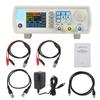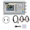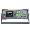
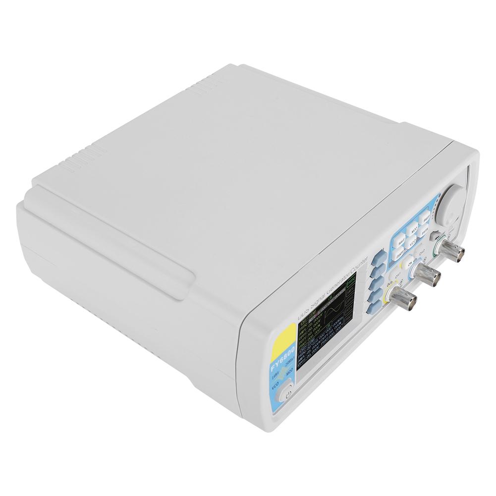
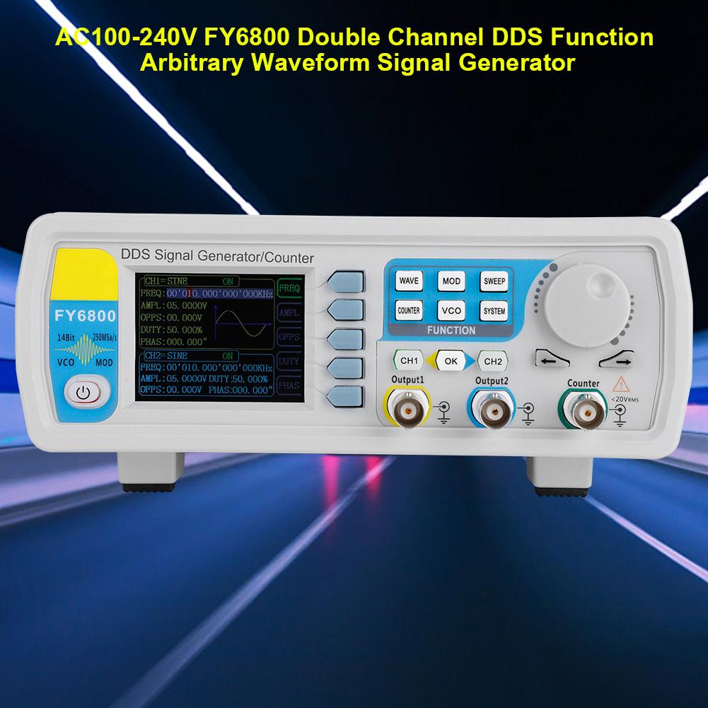
FY6800 Double Channel DDS Function Arbitrary Waveform Signal Generator(30MHz )


 Vrácení peněz při nedoručeníZáruka kvalityBezpečná logistikaOchrana soukromí
Popis
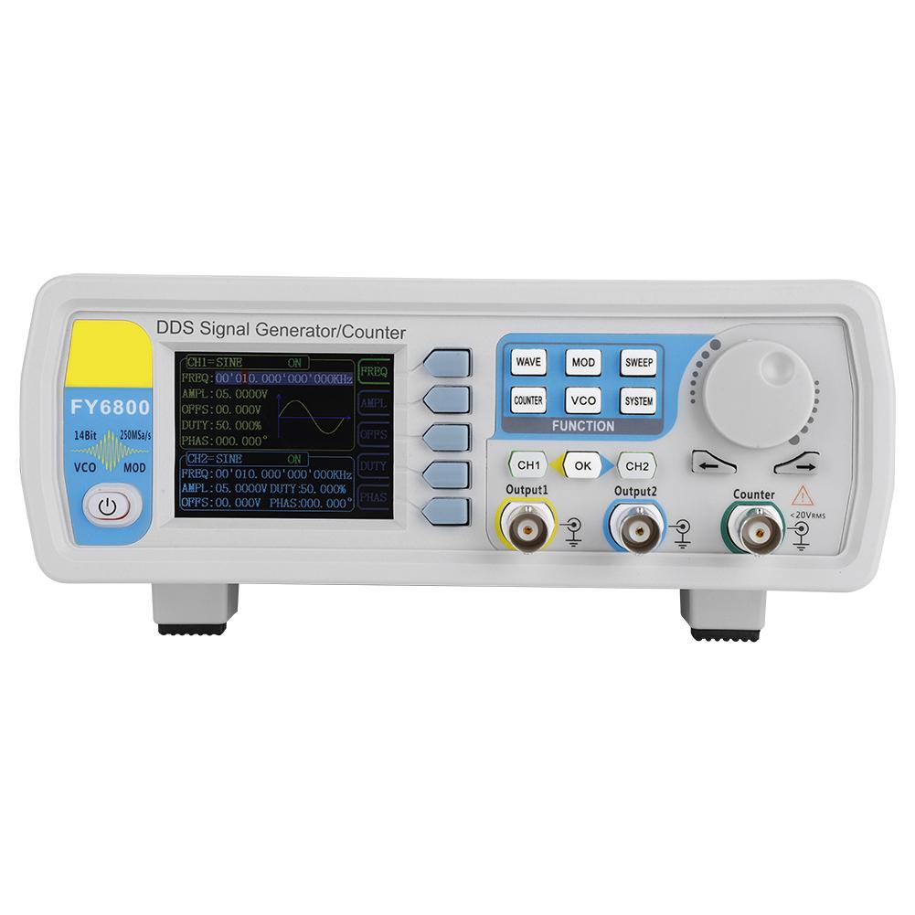
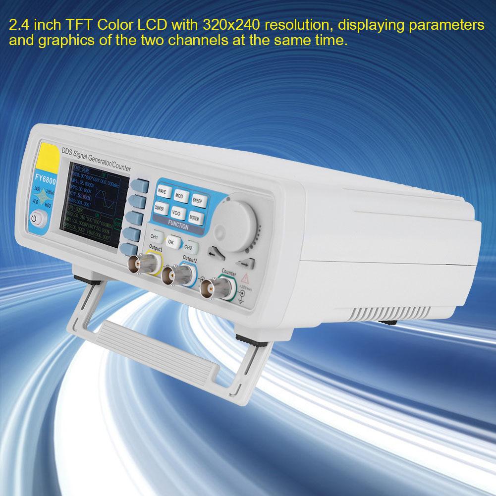
Features: Adopt the Direct Digital Synthesizer (DDS) technology and provide stable, precise, pure and low distortion signals. Desktop design with ABS plastic housing, AC 100 240V (AC) wide voltage supply; 2.4 inch TFT Color LCD with 320x240 resolution, displaying parameters and graphics of the two channels at the same time. The instrument uses 14 bit high speed D A converter chip (5Vpp output quantization error is less than 1mV), 250MSa s sample rate, 14bits vertical resolution. Fully independent dual channel output (equivalent to two independent signal sources), able to work synchronously, and the phase difference can be accurately adjusted; Equipped with channel tracking function, when the tracking function is turned on, all parameters of both channels can be updated according to the user s configuration at the same time; Two or more instruments can synchronize multiple instruments through the SYNC port; Up to 98 sets of function arbitrary waveforms can be output, including 34 sets of preset waveforms and 64 sets of user defined waveforms. Preset waveforms include: sine wave, square wave (duty ratio adjustable), triangle wave, pulse wave (preset pulse width and frequency can be precisely set), rise sawtooth wave, ramp sawtooth wave, staircase wave, trapezoidal pulse wave, Sink Pulse, narrow pulse, noise, exponential rise, exponential drop, electrocardiogram, Lorentz pulse, multiple audio waves, CMOS (0 10V), four channel TTL level and DC voltage; Enable to store 64 arbitrary waveform data files, each one of waveform storage depth 8192 points * 14bits; High frequency accuracy: Frequency accuracy can reach 10 6 orders of magnitude; The frequency resolution is relatively high: the full range frequency resolution is 1uHz (0.000001Hz); Amplitude resolution is higher: Amplitude resolution can be as low as 1mV (0.001V); With 10V +10V DC bias function (<20MHz), resolution up to 1mV; The duty cycle of both channels can be adjusted independently, with an accuracy of 0.01percent ; The phase adjustment range of the two channels is 0 359.99 degrees , and the adjustment accuracy is 0.01 degrees ; u No range limit: The full range of frequency is not divided into gear switches, program controlled settings; With digital signal output function, it can realize any CMOS level with 0 10V amplitude; Scanning function: It can scan the four properties of the signal: frequency, amplitude, offset, and duty cycle. It has two scanning modes: linear scan and logarithmic scan. The scan time can reach 999.99S. The start and end of the scan can be set arbitrarily ; Burst Output Function: There has Manual Trigger, internal CH2 Trigger, and External Trigger for your options. It can output1 1048575 pulse trains. VCO function: Support VCO voltage control signal output function (such as voltage controlled oscillator). Various modulation types: AM, FM, PM, ASK, FSK and PSK modulations. 100M Frequency meter function: It can measure frequency, period, pulse width and duty cycle. Max. frequency workable is 100MHz and Min. frequency workable is 0.01 Hz. Counter Function: It has 2 coupling measure modes including DC coupling and AC coupling. This design can solve inaccuracy problem of AC coupling. All parameters can be calibrated by internal procedures; Equipped with powerful arbitrary waveform editing function, it can edit arbitrary waveform on PC and download to instrument output waveform; Powerful communication features that can be controlled using a PC. Open communication protocol makes secondary development very simple; Standard dual full functional channels which are equivalent to two independent generators. High reliability: Large scale integrated circuit, surface mount technology, high reliability, long service life; Output short circuit protection: All signal outputs can work under load short circuit conditions 60S or more; Can choose our FYA2000S series or FPA1000 series power amplifier to output 20W 100Wsignal in DC 10MHz width without any distortion. Specification: Item Function Description 1 LCD 2.4inch TFT(320x240)color LCD. Operation instruction please check chapter User Interface . 2 Menu Buttons Menu buttons are matched with Menu displayed on the LCD. Press corresponding button to activate sub menu represented. 3 Function Buttons Area Waveform selection button:
You can switch between sine, square wave, triangle wave, and any type of arbitrary wave.
Change the selected channel signal type. Trigger and modulation function buttons
Can set a specific number of pulse train output function(BURS)
Modulation mode can be set :ASK,FSK,PSK,AM,FM,PM Sine, square, sawtooth and arbitrary waveform can be scanned.
Supports scanning of four parameters of frequency, amplitude, offset, and duty cycle. Supports two linear and logarithmic scanning methods. Can switch to frequency meter and counter function, measure frequency, period, duty cycle, positive pulse width of external input signal
Supports DC and AC signal input.
Supports 1 s, 10 s and 100 s gate time switching.
Dual channel output can work with frequency meter measurement. VCO function can be set
Support VCO voltage control signal generator s frequency, amplitude, offset, duty cycle and other parameter output functions (such as voltage controlled oscillator). Used to set auxiliary function parameters and system parameters.
Supports storage of 20 sets of parameters such as frequency, amplitude, offset, and phase
Support Chinese and English switching
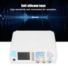
Support tone off on
Supports multi machine cascading
Supports master slave switch over in cascaded state
Supports dual channel power on default output state setting 4 Arrows Press Arrow buttons to select figure which you want to edit when setting values of each parameter. 5 ADJ Knob When using the knob to set parameters, you can increase (clockwise) or decrease (counterclockwise) the value at the current cursor. 6 Power Button The power indicator will remain on when it is turned on. When the signal generator is turned off, the indicator light will enter the breathing lamp state and CH1 and CH2 will stop outputting (the output will remain at 0 volts). 7 CH1 channel output connector BNC connector, nominal output impedance 50 Ohm . When channel CH1 is on (the CH1 button indicator lights up), the connector outputs the waveform in the current configuration of CH1. 8 Channel control,OK button It is used to control the output of the CH1 channel and can be switched to the CH1 parameter setting interface in any interface.
Press this button, the CH1 light will turn on, and the CH1 output will turn on. At this point, the (CH1) connector outputs the signal in the current configuration.
Press this button again, the indicator light goes off, and at this point, the CH1 output is turned off. Confirm button
When editing frequency parameters, press this key to change the frequency unit.
When scanning the interface, press this button to start stop scanning. It is used to control the output of the CH1 channel and can be switched to the CH1 parameter setting interface in any interface.
Press this button, the CH2 light will turn on, and the CH2 output will turn on. At this point, the (CH2) connector outputs the signal in the current configuration.
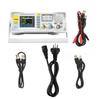
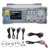
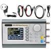
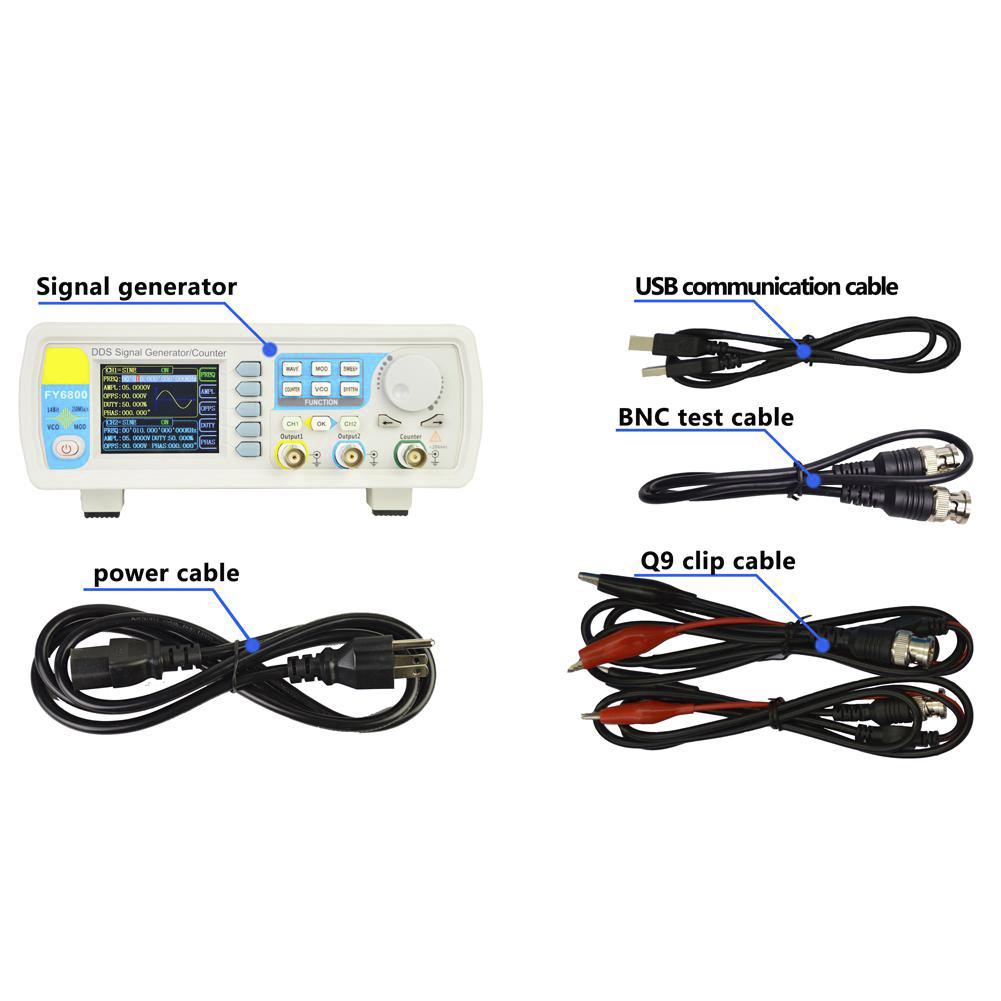
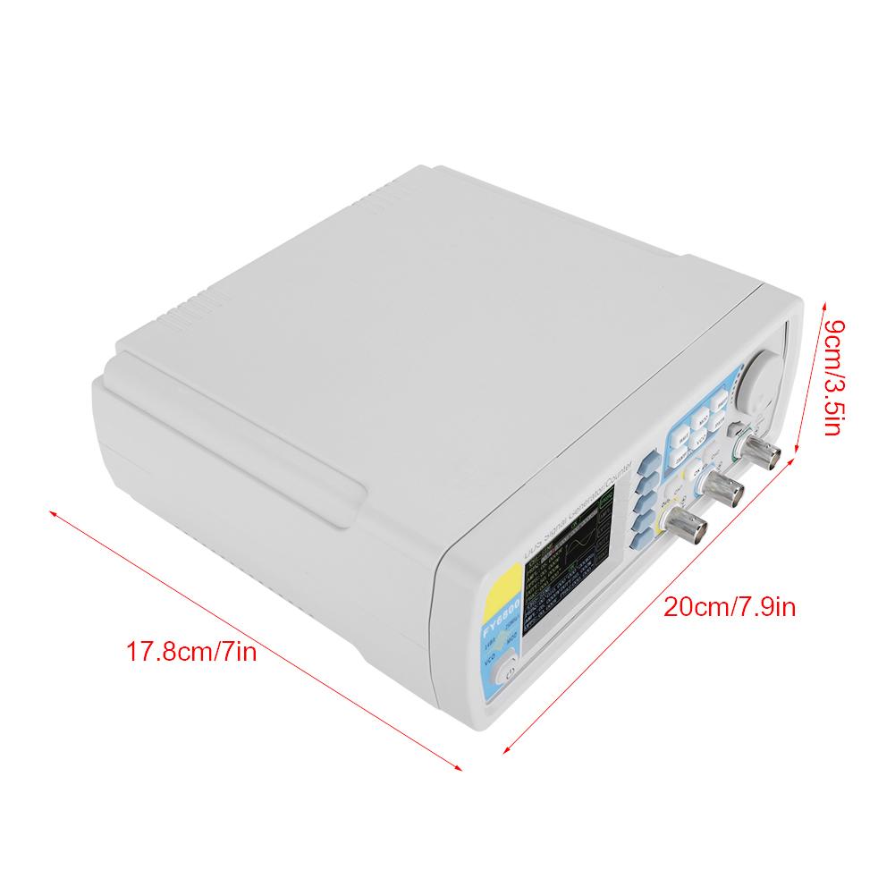
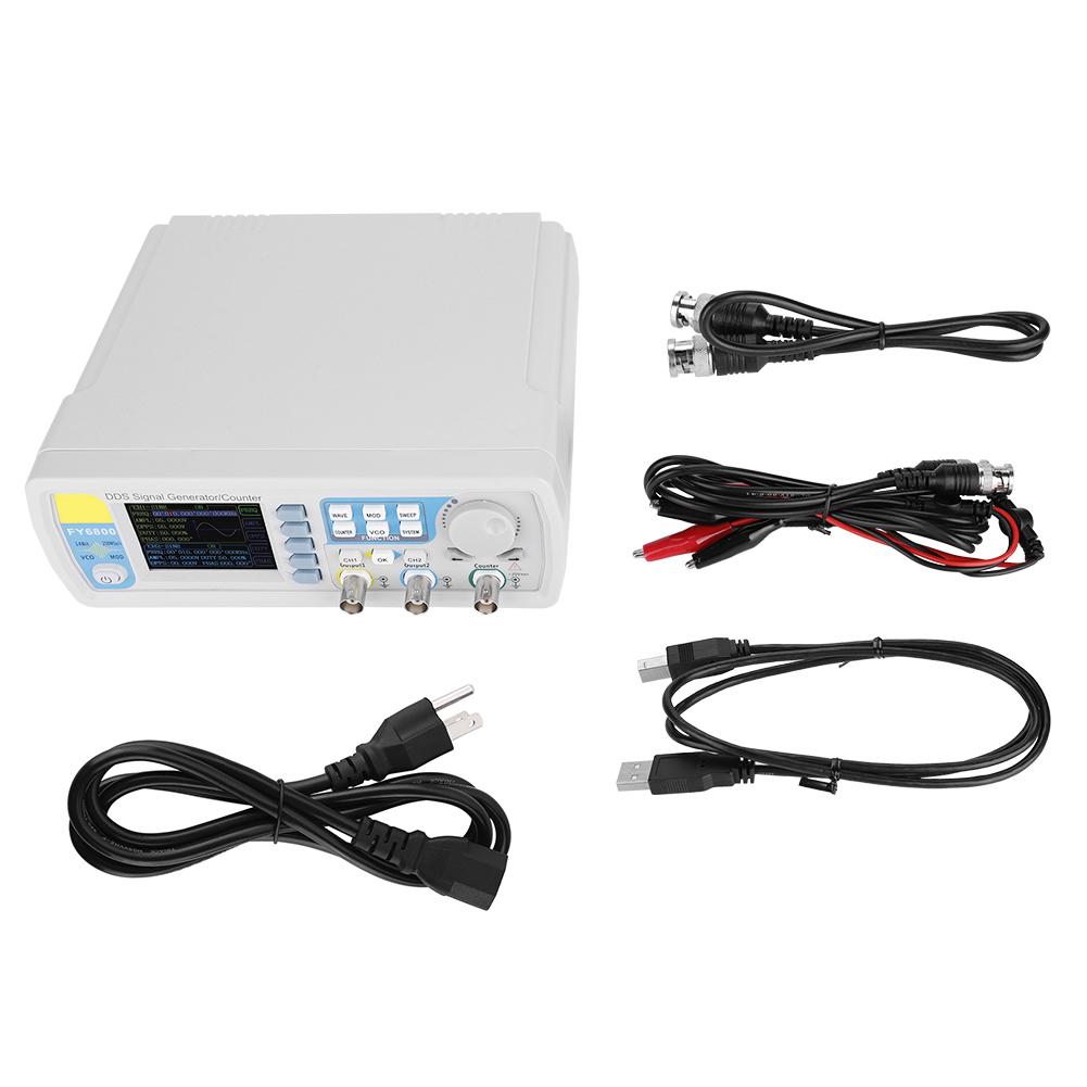
Press this button again, the indicator light goes off, and at this point, the CH2 output is turned off. 9 CH2 channel output connector BNC connector, nominal output impedance 50 Ohm . When channel CH2 is on (the CH2 button indicator lights up), the connector outputs the waveform in the current configuration of CH2. 10 AC coupling measuring terminal BNC connector, input impedance 100 Ohm . For inputting signal of meter or counter. 11 Model FY6800 12 Voltage 100 240V 13 Type (Optional) 30MHz US plug, 30MHz EU plug, 60MHz US plug, 60MHz EU plug, 30MHz UK plug, 60MHz UK plug 14 Size 20*17.8*9cm 7.9*7*3.5in 15 Weight Approx.1107g 39oz Detail: The back panel of FY6800is as picture 1 2 below. 4 BNC terminals on the left are DC coupling measuring terminals Trig FSK ASK PSK IN, external sweep input VCO IN, Synchronization output connector SYNC OUT, and Synchronization input connector SYNC IN. Then follows TTL output terminal, USB terminal, power switch and power input socket. 1. BNC connector Trig FSK ASK PSK IN: DC coupling measuring terminal and ASK PSK FSK modulation trigger input terminal. VCO IN: External signal sweep input terminal can realize voltage controlling frequency, voltage controlling amplitude, voltage controlling offset, voltage controlling duty cycle and so on. Frequency of external signal input should be lower than 500 Hz. SYNC OUT: Synchronization signal output terminal. SYNC IN: Synchronization signal input terminal. 2. TTL signal output Frequency of Port A is same with frequency of CH1 output. Frequency of Port B is same with frequency of Port A but with reverse phase (180 degrees ). Frequency of Port C is same with frequency of CH2. Frequency of Port D is same with Port C but with reverse phase (180 degrees ). 3. USB Device interface It s for communication with PC (This is a USB TTL serial port and driver is needed). Can program by host computer. 4.Power switch&Power input socket(voltage range AC100V AC240V). Package list: 1 x FY6800 signal generator 1 x Power Cable 1 x USB Cable 1 x BNC BNC Connection Cable 2 x BNC Clip Cable