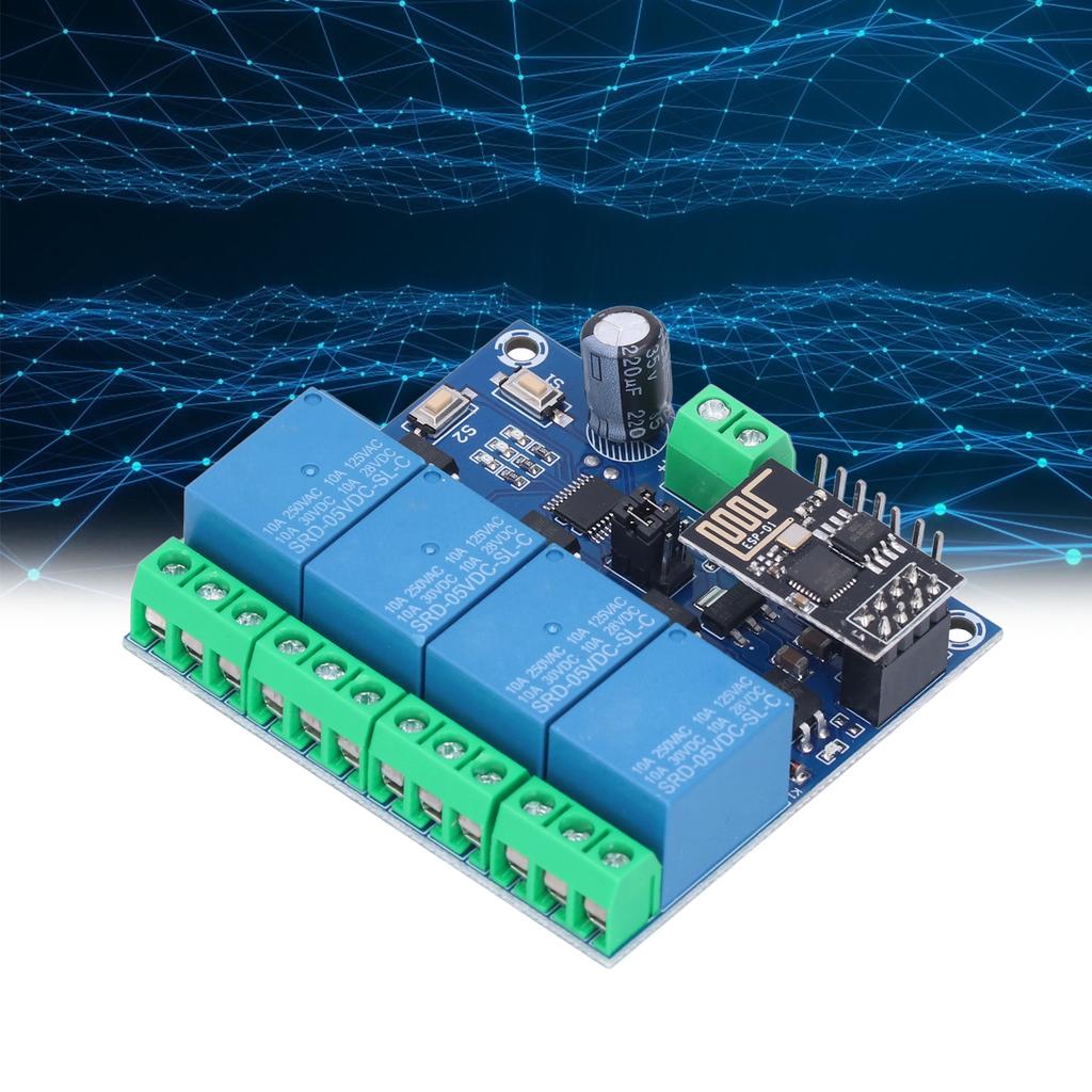
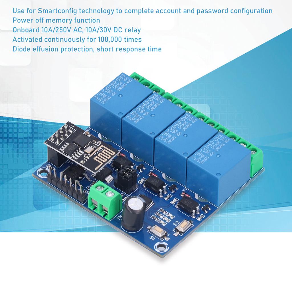
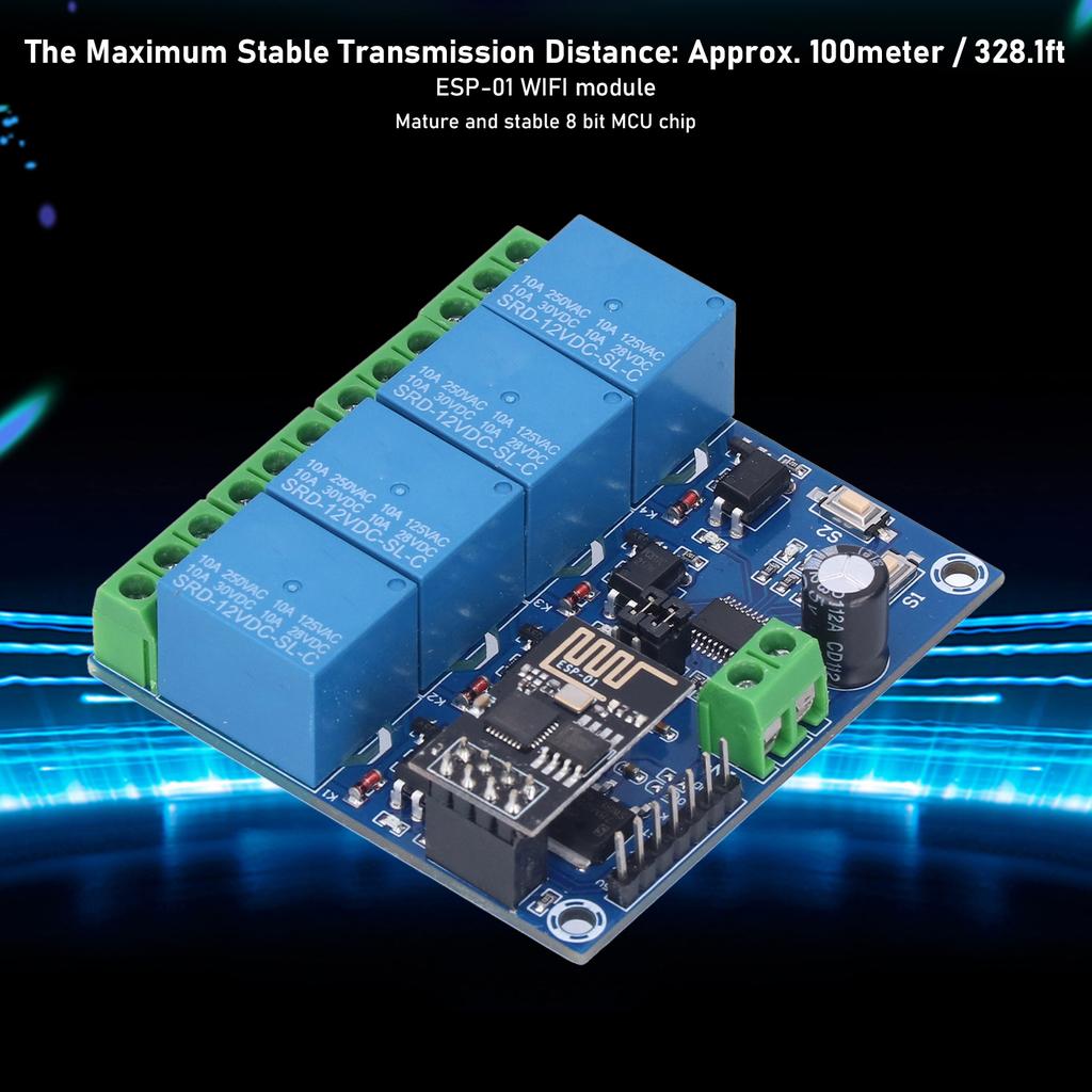
8 Bit MCU Chip: The 8266 WIFI relay module uses 01 as the WIFI module, with a mature and stable 8 bit MCU chip
Simple Configuration Process: NaOnly a simple configuration process can rlize the wireless control of the relay in the local ar using the mobile phone APP, onboard mode NaSelection and rl time working status indicator
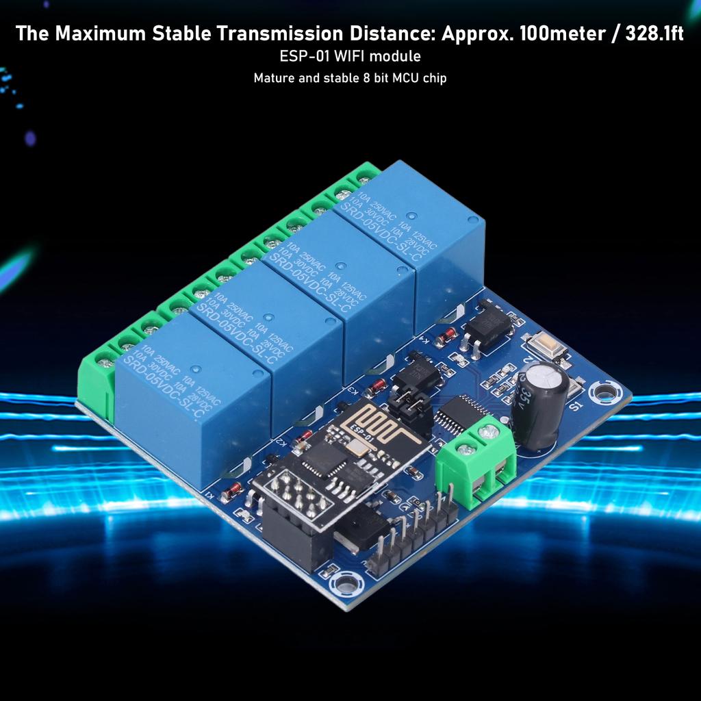
100meter Maximum : The maximum stable distance is up to 100meter when the mobile phone is mounted on the WIFI module in an open environment
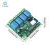
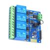
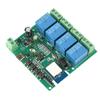
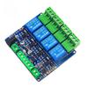
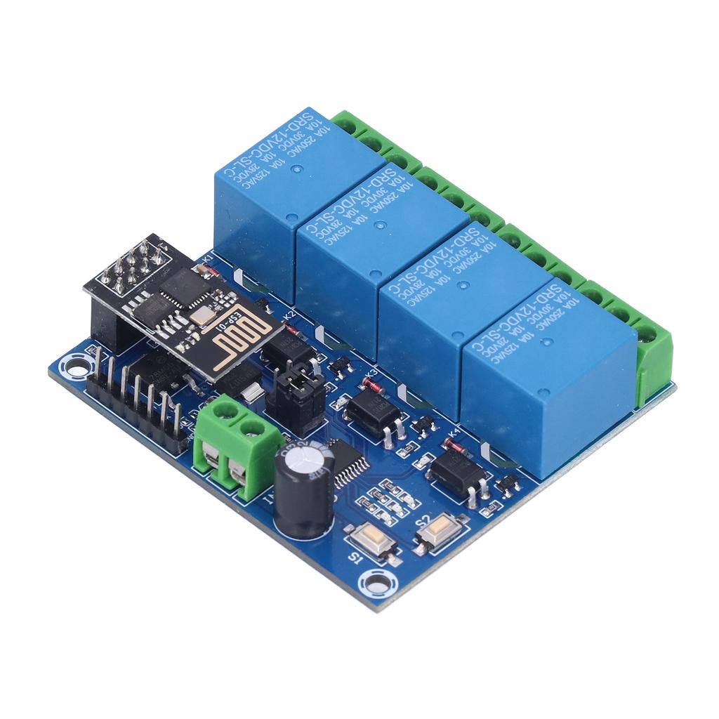
Item Type: WiFi Relay Module
Onboard: High performance microprocessor and -01WIFI module
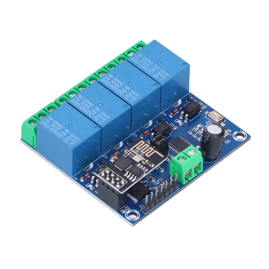
2 Working Modes:
The mobile phone is directly mounted on the WIFl module; the mobile phone and the WIFI module are both mounted on the router
Additional Function: Can be used as a USB relay when -01 is unplugged
Distance:
The Maximum Stable Distance: Approx. 100meter / 328.1ft
When the WIFI module and mobile phone are mounted on the router at the same time, the distance depends on the signal strength of the router
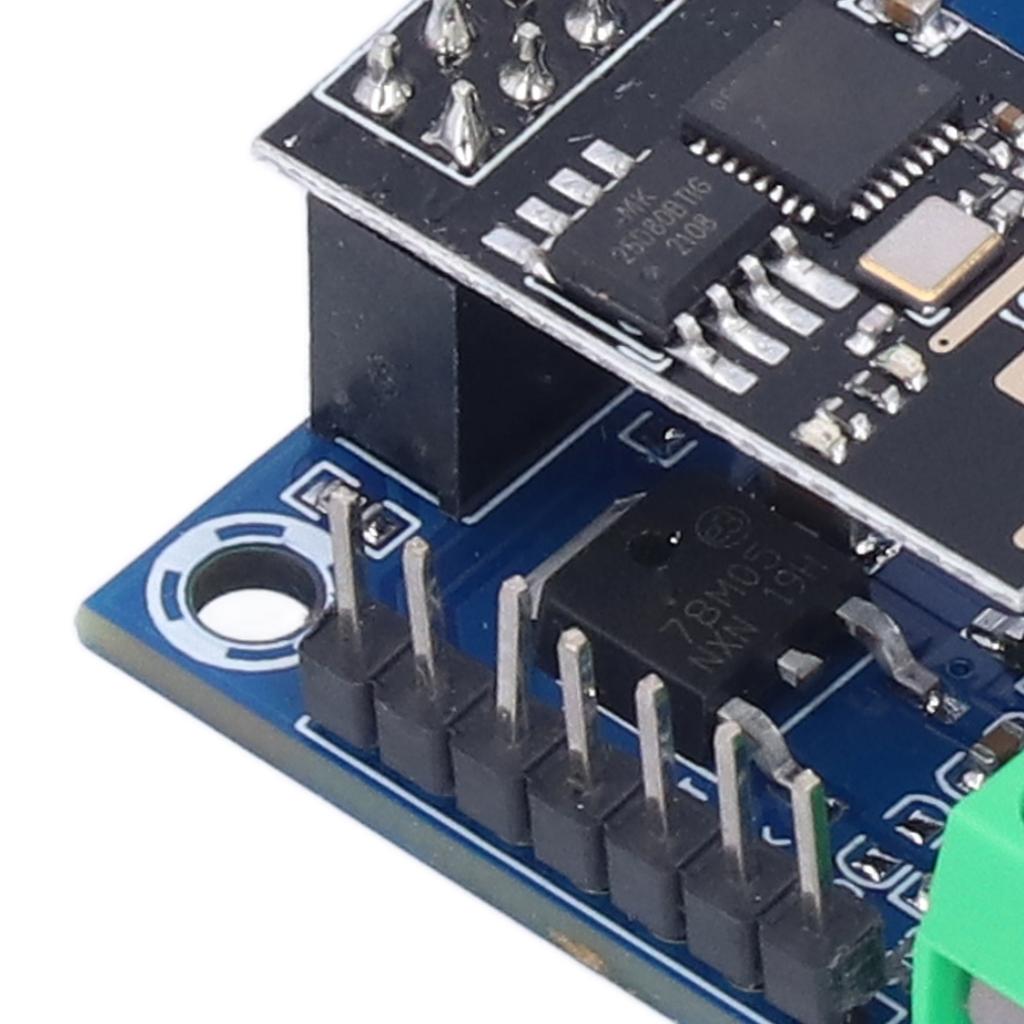
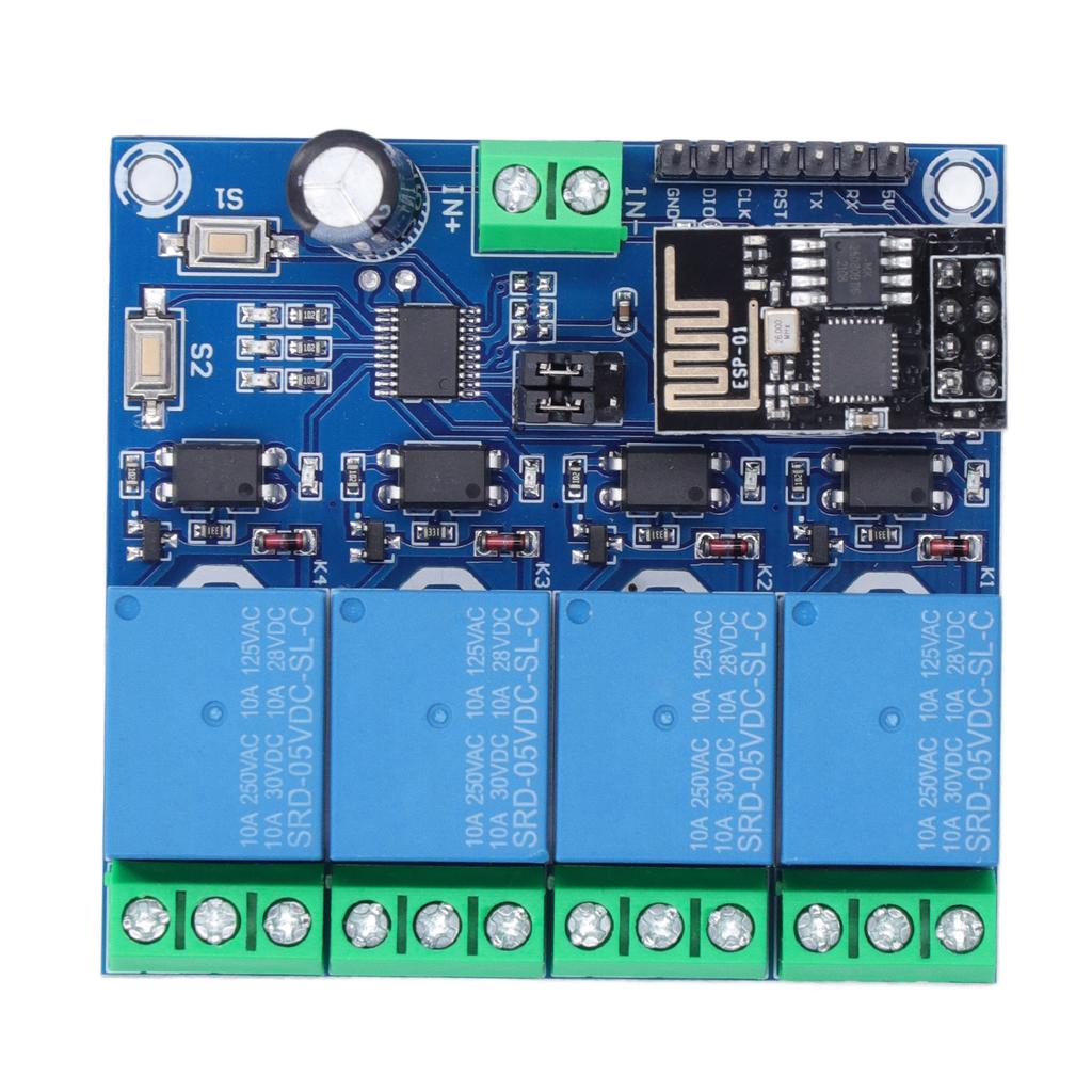
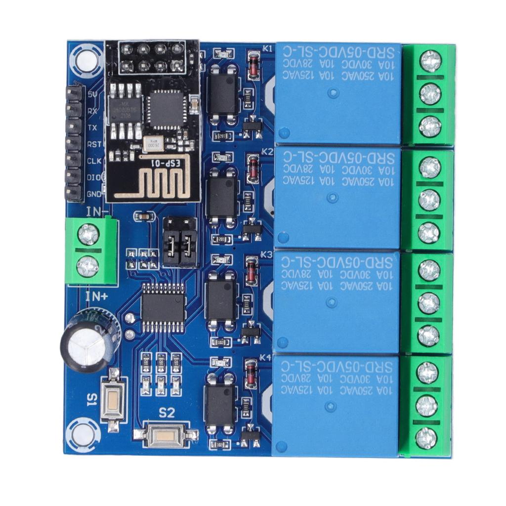
Reserved: UART debugging interface and MCU program download interface
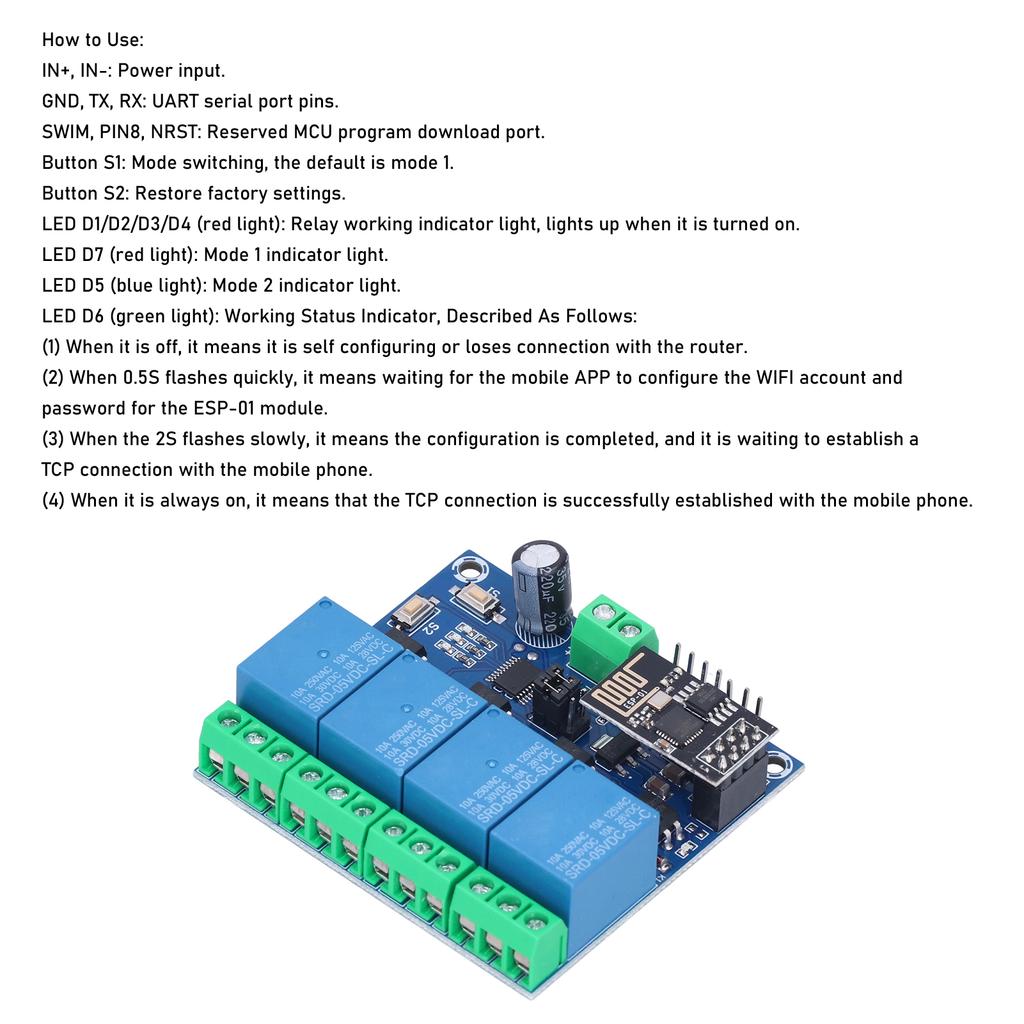
How to Use:
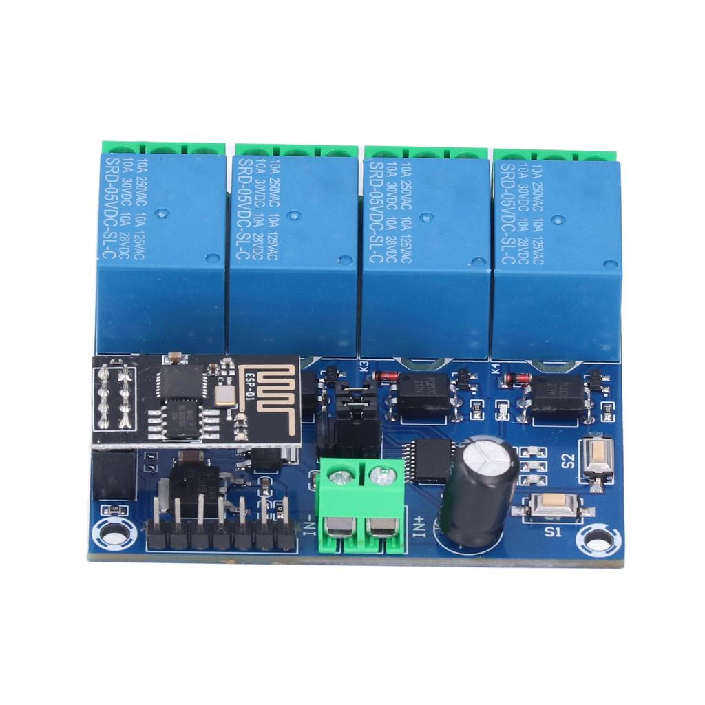
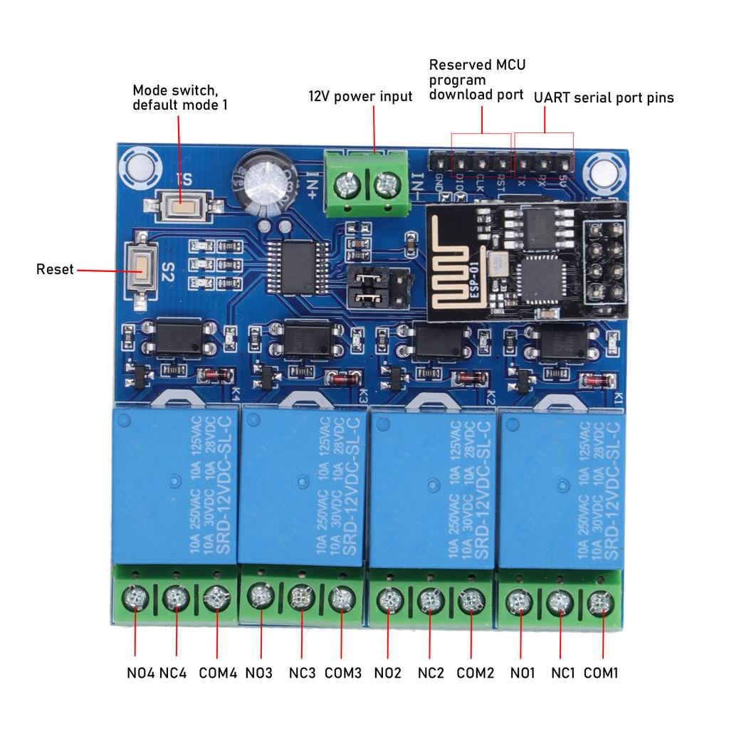
IN+, IN-: Power input.
GND, TX, : UART serial port pins.
SWIM, PIN8, NRST: Reserved MCU program download port.
Button S1: Mode ing, the default is mode 1.
Button : factory settings.
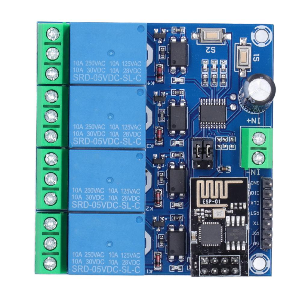
LED D1/D2/D3/D4 (red light): Relay working indicator light, lights up when it is turned on.
LED D7 (red light): Mode 1 indicator light.
LED D5 (blue light): Mode 2 indicator light.
LED D6 (green light): Working Status Indicator, Described As Follows:
(1) When it is off, it mns it is self configuring or loses connection with the router.
(2) When 0.5S flashes quickly, it mns waiting for the mobile APP to configure the WIFI account and password for the -01 module.
(3) When the 2S flashes slowly, it mns the configuration is completed, and it is waiting to establish a connection with the mobile phone.
(4) When it is always on, it mns that the connection is successfully established with the mobile phone.
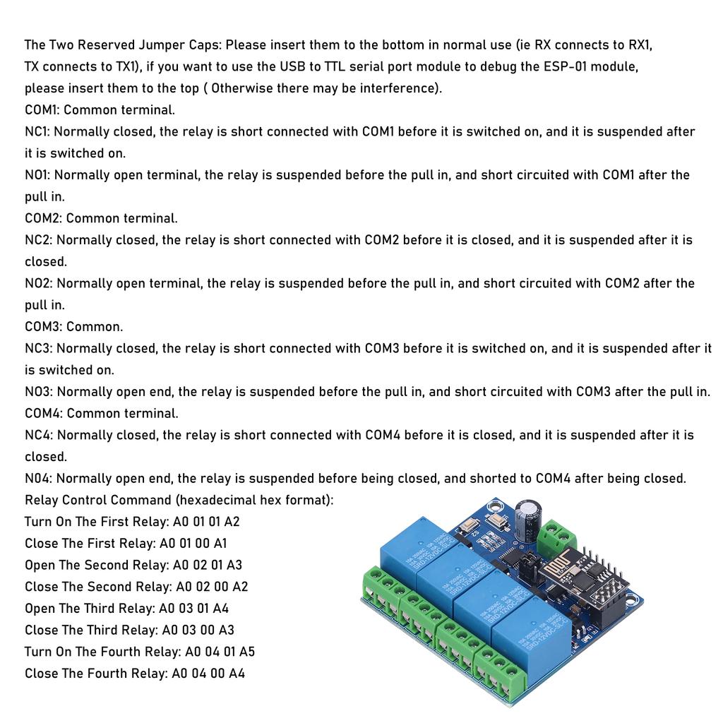
The Two Reserved : Plse insert them to the bottom in normal use (ie connects to 1, TX connects to TX1), if you want to use the USB to TTL serial port module to debug the -01 module, plse insert them to the top ( Otherwise there may be interference).
COM1: Common terminal.
NC1: Normally closed, the relay is short connected with COM1 before it is ed on, and it is suspended after it is ed on.
NO1: Normally open terminal, the relay is suspended before the pull in, and short circuited with COM1 after the pull in.
COM2: Common terminal.
NC2: Normally closed, the relay is short connected with COM2 before it is closed, and it is suspended after it is closed.
NO2: Normally open terminal, the relay is suspended before the pull in, and short circuited with COM2 after the pull in.
COM3: Common.
NC3: Normally closed, the relay is short connected with COM3 before it is ed on, and it is suspended after it is ed on.
NO3: Normally open end, the relay is suspended before the pull in, and short circuited with COM3 after the pull in.
COM4: Common terminal.
NC4: Normally closed, the relay is short connected with COM4 before it is closed, and it is suspended after it is closed.
N04: Normally open end, the relay is suspended before being closed, and shorted to COM4 after being closed.
Relay Control NaCommand (hexadecimal hex format):
Turn On The First Relay: A0 01 01 A2
Close The First Relay: A0 01 00 A1
Open The Second Relay: A0 02 01
Close The Second Relay: A0 02 00 A2
Open The Third Relay: A0 03 01
Close The Third Relay: A0 03 00
Turn On The Fourth Relay: A0 04 01
Close The Fourth Relay: A0 04 00


 Vrácení peněz při nedoručení